Private Cloud Architecture

Part: 1
Definitions 

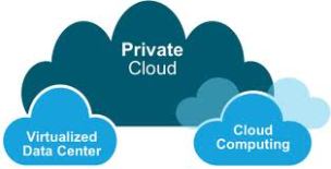
Private Cloud Private cloud is cloud infrastructure operated solely for a single organization, whether managed internally or by a third-party and hosted internally or externally. Undertaking a private cloud project requires a significant level and degree of engagement to virtualize the business environment, and requires the organization to reevaluate decisions about existing resources. When done right, it can have improve business, but every step in the project raises security issues that must be addressed to prevent serious vulnerabilities. Meanwhile, Provides Computer Power, Storage and Networking infrastructure (such as firewalls and load balances) as a service via own organization data center or Via third party Local Hosts or Cloud – over the internet – Hosts.

Private Cloud Architecture: 

IaaS – Infrastructure as a Service: In the most basic cloud-service model, providers of IaaS offer computers – physical or (more often) virtual machines – and other resources. A Hyper-Visor runs the virtual machines as guests. Pools of hyper-visors within the cloud operational support-system can support large numbers of virtual machines and the ability to scale services up and down according to customers’ varying requirements.) IaaS clouds often offer additional resources such as images in a virtual-machine image-library. IaaS-cloud providers supply these resources on-demand from their large pools installed in Data centers for Wide Area connectivity.

PaaS – Platform as a Service: In the PaaS model, cloud providers deliver a computing platform  typically including operating system, programming language execution environment, database, and web server. Application developers can develop and run their software solutions on a cloud platform without the cost and complexity of buying and managing the underlying hardware and software layers. With some PaaS offers, the underlying computer and storage resources scale automatically to match application demand such that cloud user does not have to allocate resources manually.

SaaS – Software as a Service: In the SaaS model, cloud providers install and operate application software in the cloud and cloud users access the software from cloud clients. Cloud users do not manage the cloud infrastructure and platform where the application runs. This eliminates the need to install and run the application on the cloud user’s own computers, which simplifies maintenance and support. Cloud applications are different from other applications in their scalability, which can be achieved by cloning tasks onto multiple virtual machines at run-time to meet changing work demand.

Simply, Private Cloud offers a package of software and services is offered through a service delivery mechanism similar to that of a public utility such as telephone, internet, electricity, water or gas. These services have the advantage of low initial cost and a “pay as you go” pricing model. A Cloud-Provider exploits the benefits of Cloud Infrastructure to provide on demand computing power for its distributed web applications which can be delivered worldwide at a low cost of ownership under very reliable service level agreements which ensure flexibility and continuity in work and business.

Network Load Balance

Background Information

Network Load Balancing (NLB) technology can be used to distribute client requests across a set of servers. In order to make sure clients always experience acceptable performance levels, Windows NLB is often used to ensure that you can add additional servers to scale out stateless applications, such as IIS-based web servers, as client load increases. In addition, it reduces downtime caused by servers that malfunction. End users will never know that a particular member server in the Windows NLB is or has been down.

Network Load Balancing is a clustering technology offered by Microsoft as part of all Windows 2000 Server and Windows Server 2003 family operating systems. NLB uses a distributed algorithm to load balance network traffic across a number of servers.

NLB bundles the servers into one multicast group and tries to use the standard multicast IP and MAC address. At the same time, it provides a single virtual IP for all clients as the destination IP, which means servers join the same multicast group, and the clients will not know anything about it. They use normal unicast access to the VIP.

You can configure NLB to work in one of these modes:

Unicast Mode

The NLB default setting is unicast mode. In unicast mode, NLB replaces the actual MAC address of each server in the cluster to a common NLB MAC address. When all the server in the cluster have the same MAC address, all packets forwarded to that address are sent to all members of the cluster. However, a problem with this configuration is when the servers NLB cluster are connected to the same switch, you cannot have two ports on the switch register the same MAC address. NLB solves this problem by masking the cluster MAC address. The switch looks at the source MAC address in the Ethernet frame header in order to learn which MAC addresses are associated with its ports. NLB creates a bogus MAC address and assigns that bogus MAC address to each server in the NLB cluster. NLB assigns each NLB server a different bogus MAC address based on the host ID of the member. This address appears in the Ethernet frame header.

For example, the NLB cluster MAC address is 00-bf-ac-10-00-01. NLB in unicast mode takes the cluster MAC address and, for each cluster member, NLB changes the second octet so that it consists of the NLB member’s host ID. For example, server number 1 as the bogus MAC address 00-01-ac-10-00-01, host ID number 2 has the bogus MAC address 00-02-ac-10-00-01, so on. If a unique MAC address is registered on each switch port, packets are not delivered to all members of the array; rather packets should still be sent to the individual switch ports based on the MAC address assigned to that port. To make frames delivered to all members of the NLB cluster when each switch port connected to an NLB cluster member registers a different MAC address it uses an ARP broadcast are used. When the router sends an ARP request for the MAC address of the virtual IP address, the reply contains an ARP header with the actual NLB cluster MAC address 00-bf-ac-10-00-01, as per the example given above and not the bogus MAC address.

The clients use the MAC address in the ARP header, not the Ethernet header. The switch uses the MAC address in the Ethernet header, not the ARP header. The issue is when a client sends a packet to the NLB cluster with destination MAC address as cluster MAC address 00-bf-ac-10-00-01, the switch looks at the CAM table for the MAC address 00-bf-ac-10-00-01. Since there is no port registered with the NLB cluster MAC address 00-bf-ac-10-00-01, the frame is delivered to all switch ports. This introduces switch flooding. Switch flooding causes issues when significant amount of traffic is flowing and also when having other servers on the same switch. A solution to switch flooding is to put a simple hub in front of the NLB cluster members and then uplink the hub to a switch port. This solution does not even need to mask the NLB cluster MAC address because the single switch port connected to the hub learns the NLB cluster MAC address. This avoids the problem of two switch ports registering the same MAC address. When the client sends packets to the NLB cluster MAC address, the packets go directly to the switch port connected to the hub and then to the NLB cluster members.

Multicast Mode

Another solution is to use multicast mode in MS NLB configuration GUI instead of Unicast mode. In Multicast Mode, the system admin clicks the IGMP Multicast button in the MS NLB configuration GUI. This choice instructs the cluster members to respond to ARPs for their virtual address using a multicast MAC address for example 0300.5e11.1111 and to send IGMP Membership Report packets. If IGMP snooping is enabled on the local switch, it snoops the IGMP packets that pass through it. In this way, when a client ARPs for the cluster’s virtual IP address, the cluster responds with multicast MAC for example 0300.5e11.1111. When the client sends the packet to 0300.5e11.1111, the local switch forwards the packet out each of the ports connected to the cluster members. In this case, there is no chance of flooding the ARP packet out of all the ports. The issue with the multicast mode is virtual IP address becomes unreachable when accessed from outside the local subnet because Cisco devices do not accept an arp reply for a unicast IP address that contains a multicast MAC address. So the MAC portion of the ARP entry shows as incomplete. (Issue the command show arp to view the output.) As there is no MAC portion in the arp reply, the ARP entry never appeared in the ARP table. It eventually quit ARPing and returned an ICMP Host unreachable to the clients. In order to override this, use static ARP entry to populate the ARP table as given below. In theory, this allows the Cisco device to populate its mac-address-table. For example, if the virtual ip address is 172.16.63.241 and multicast mac address is 0300.5e11.1111, use this command in order to populate the ARP table statically:

arp 172.16.63.241 0300.5e11.1111

However, since the incoming packets have a unicast destination IP address and multicast destination MAC the Cisco device ignores this entry and process-switches each cluster-bound packets. In order to avoid this process switching, insert a static mac-address-table entry as given below in order to switch cluster-bound packets in hardware.

mac-address-table static 0300.5e11.1111 vlan 200 interface

         fa2/3 fa2/4

Note: For Cisco Catalyst 6000/6500 series switches, you must add the disable-snopping parameter. For example:

mac-address-table static 0300.5e11.1111 vlan 200

               interface fa2/3 fa2/4 disable-snooping

The disable-snooping parameter is essential and applicable only for Cisco Catalyst 6000/6500 series switches. Without this statement, the behavior is not affected.

Configure

In this section, you are presented with the information to configure the features described in this document.

Note: Use the Command Lookup Tool  to obtain more information on the commands used in this section.

Network Diagram

This Post uses this network setup:

Configurations

This Post uses the Catalyst 6509 configuration described in this section.

Configuration Using Catalyst 6509

Cat6K#show running-config

 Building configuration…

!

version 12.1

service timestamps debug uptime

service timestamps log uptime

no service password-encryption

!

hostname Cat6K

!

boot buffersize 126968

boot system flash slot0:c6sup11-jsv-mz.121-8a.E.bin

!

redundancy

 main-cpu

  auto-sync standard

ip subnet-zero

!

!

interface GigabitEthernet1/1

 no ip address

 shutdown

!

interface GigabitEthernet1/2

 no ip address

 shutdown

!

interface FastEthernet2/1

 description “Uplink to the Default Gateway”

 no ip address

 switchport

 switchport access vlan 100

!

interface FastEthernet2/2

 no ip address

 shutdown

!

interface FastEthernet2/3

 description “Connection to Microsoft server”

 no ip address

 switchport

 switchport access vlan 200

!

interface FastEthernet2/4

 description “Connection to Microsoft server”

 no ip address

 switchport

 switchport access vlan 200

!

interface FastEthernet2/5

 no ip address

 shutdown

!

interface FastEthernet2/48

 no ip address

 shutdown

!

interface Vlan1

 no ip address

 shutdown

!

mac-address-table static 0300.5e11.1111 vlan 200 interface fa2/3 fa2/4 disable-snooping


! — Creating a static entry in the switch for the multicast virtual mac.


! — fa2/3 & fa2/4 are the ports connected to server.


!— The disable-snooping is applicable only for Cisco Catalyst 6000/6500 series switches

arp 172.16.63.241 0300.5e11.1111


! — 172.16.63.241 is the Virtual IP of 2 servers

interface Vlan100

 ip address 172.17.63.240 255.255.255.192


!— Client Side Vlan

!

interface Vlan200

 ip address 10.1.1.250 255.255.255.0


!— Server Vlan


!— Important: Configure the default gateway


!— of the Microsoft Server to this address.

!

ip classless

ip route 0.0.0.0 0.0.0.0 172.16.63.193

no ip http server

!

line con 0

line vty 0 4

 login

!

end

Note: Ensure that you use the multicast mode on the NLB cluster. Cisco recommends that you do not use multicast MAC addresses that begin with 01 because they are known to have a conflict with the IGMP setup.

Verify

Use this section to confirm that your configuration works properly.

The Output Interpreter Tool (OIT) supports certain show commands. Use the OIT to view an analysis of show command output.

  • show mac-address-table—Displays a specific MAC address table static and dynamic entry or the MAC address table static and dynamic entries on a specific interface or VLAN.
  • Cat6K#show mac-address-table 0300.5e11.1111
  •           Mac Address Table
  • ——————————————-
  • Vlan    Mac Address       Type        Ports
  • —-    ———–      ——–     —–

200    0300.5e11.1111     STATIC    Fa2/3 Fa2/4

  • show ip arp—Displays the Address Resolution Protocol (ARP) cache.
  • Cat6K#show ip arp
  • Protocol  Address          Age (min)  Hardware Addr   Type   Interface
  • Internet  172.16.1.1            –     0300.5e11.1111  ARPA   Vlan200

Failover Clustering Overview

Overview

Server availability is a higher priority than ever. The demands of a “24×7” global marketplace mean downtime can equate to lost customers, revenue, and productivity.

 Image

Windows Server 2008 brought many new or enhanced configuration, management, and diagnostic features to failover clustering that made setting up and managing the clusters easier for IT staff. Windows Server 2008 R2 builds on that work with improvements aimed at enhancing the validation process for new or existing clusters, simplifying the management of clustered virtual machines (which run with Hyper-V), providing a Windows PowerShell interface, and providing more options for migrating settings from one cluster to another. These enhancements combine to provide you with a near turn-key solution for making applications and services highly available.

Cluster Validation Tool

By using the Cluster Validation Tool, you can perform tests to determine whether your system, storage, and network configuration is suitable for a cluster. The Cluster Validation Tool verifies that the nodes meet all of the operating system requirements, that the networks are configured correctly, that there are at least two separate networks on each node for redundancy, and that the storage subsystem supports clustering.

Cluster Setup

Once validated by the Cluster Validation Tool, the installation has been streamlined so that administrators can set up a cluster in just a few clicks. The cluster installation is completely scriptable, enabling administrators to automate cluster deployments.

Cluster Migration

When migrating a clustered service setting can be captured and copied to another cluster. This reduces the time it takes to build the new cluster and configure the services. Administrators can migrate cluster workloads currently running on Windows Server 2003 and Windows Server 2008 to Windows Server 2008 R2. The migration process supports every workload currently supported on Windows Server 2003 and Windows Server 2008.

Cluster Management and Operations

The cluster management interface has been optimized to make managing the cluster easier and more intuitive. Cluster management can be performed from the command line as well as the Windows Management Instrumentation (WMI) management console.

Cluster Backup and Restore

Full integration with the Volume Shadow Copy Service makes it easier to back up and restore cluster configurations.

Cluster Infrastructure

With Windows Server 2008 R2, you can configure a cluster so that the quorum resource, which contains the cluster configuration settings, is not a single point of failure.

Cluster Storage

Administrators have better control and can achieve better performance with storage than was possible in previous releases. Failover clusters now support GUID partition table (GPT) disks that can have capacities of larger than 2 terabytes, for increased disk size and robustness. Administrators can now modify resource dependencies while resources are online, which means they can make an additional disk available without interrupting access to the application that will use it. And administrators can run tools in Maintenance Mode to check, fix, back up, or restore disks more easily and with less disruption to the cluster.

Cluster Network

Networking has been enhanced to support Internet Protocol version 6 (IPv6) as well as Domain Name System (DNS) for name resolution, removing the requirement to have WINS and NetBIOS name broadcasts. Other network improvements include managing dependencies between network names and IP addresses: If either of the IP addresses associated with a network name is available, the network name will remain available. Because of the architecture of Cluster Shared Volumes (CSV), there is improved cluster node connectivity fault tolerance that directly affects Virtual Machines running on the cluster. The CSV architecture implements a mechanism, known as dynamic I/O redirection, in which I/O can be rerouted within the failover cluster based on connection availability.

Cluster Security

Internet Protocol security (IPsec) can be used between clients and the cluster nodes, as well as between nodes so that you can authenticate and encrypt the data. Access to the cluster can also be audited to determine who connected to the cluster and when.

Benefits

Windows Server Failover Clustering is an important feature of the Windows Server platform that can help improve your server availability. When one server fails, another server begins to provide service in its place. This process is called failover. Failover clusters in Windows Server 2008 R2 provide you with seamless easy-to-deploy high availability for important databases, messaging servers, file and print services, and virtualized workloads.

With failover clustering you can help build redundancy into your network and eliminate single points of failure. The improvements to failover clustering in Windows Server 2008 R2 are aimed at simplifying clusters, making them more secure, and enhancing cluster stability.

Private Cloud Attributes

Private Cloud Attributes

A great way to simplify the concept of Private Cloud is to list the key attributes of cloud computing using non-technical terminology that non IT specialists can understand. Buyers of IT products and services can use such a list to determine where their computing resources sit on the cloud computing spectrum. They can also use it as a roadmap to determine what needs to be undertaken or negotiated in order to reap the benefits of Private Cloud.

14 key attributes of Private Cloud are as follows:

1. Private Cloud offerings are services, not products.

2. Private Cloud allows customers to increase and decrease the number of users that have access to services.

3. Private Cloud allows customers to provision new services to users instantly.

4. Private Cloud turns computing resources into operational expenses rather than capital expenditure

5. Private Cloud enables organizations to pay for computing resources based on consumption of the resources in question.

6. Private Cloud allows multiple, diverse customers to share computing resources

7. Private Cloud service enhancements, such as updates, are automatic

8. Private Cloud integrates security into services.

9. Private Cloud eliminates the need for support contracts.

10. Private Cloud costs less than on-premise alternatives.

11. Private Cloud allows the purchase of services without human interaction.

12. Private Cloud integrates automatic backup into services.

13. Private Cloud services are delivered from remote locations.

14. Private Cloud services are delivered via the Internet.

The private cloud model provides much of the efficiency and agility of cloud computing along with the increased control and customization achieved through dedicated private resources.

Private Cloud Concept

Private Cloud

 Image

A Comparative Look at Functionality, Benefits, and Economics

Private Cloud

Private cloud is a computing model that uses resources which are dedicated to your organization. A private cloud shares many of the characteristics of public cloud computing including resource pooling, self-service, elasticity and pay-by-use delivered in a standardized manner with the additional control and customization available from dedicated resources.

A private cloud transforms your datacenter. Building on your existing investments and skill sets, you can now get true cloud computing capabilities that help deliver new levels of agility, focus, and cost-efficiency. With the advanced capabilities of Windows Server 2012 and System Center 2012, a Microsoft private cloud provides a range of powerful benefits across your IT environment.

Private cloud solutions are built using Windows Server with Hyper-V and System Center – the combination of which provides enterprise class virtualization, end-to-end service management and deep insight into applications so you can focus more attention on delivering business value.

Private Cloud is a unique and comprehensive offering, built on four keys:

  • All about the App: Application centric cloud platform that helps you focus on business value.
  • Cross-Platform from the Metal Up: Cross-platform support for multi-hypervisor environments, operating systems, and application frameworks.
  • Foundation for the Future: private cloud lets you go beyond virtualization to a true cloud platform.
  • Cloud on your Terms: Ability to consume cloud on your terms, providing you the choice and flexibility of a hybrid cloud model through common management, virtualization, identity and developer tools.

All about the App

To gain a real edge, you need to go beyond just managing infrastructure. You need to manage your applications in a new way. A private cloud helps you deliver apps faster, keep them up and running more reliably, and ultimately enable more predictable service level agreements.

Cross-Platform from the Metal Up

IT environments today encompass a wide range of OS, hypervisor, and development tools. The private cloud is designed to let you comprehensively support your heterogeneous IT environment, leveraging your investments and maximizing your development skill sets. Now you can keep what you have and make the move to a new kind of agility.

Foundation for the Future

Cloud computing offers the promise of new levels of agility through advanced capabilities, ultimately opening new avenues of innovation for your business. The private cloud enables a flexible, highly-available infrastructure that can scale to meet the most advanced enterprise requirements. With built-in automation and new file and storage services, you can get more power from your datacenter and realize greater value from your investments.

Cloud on Your Terms


The move to cloud computing involves more than just building a private cloud. The challenge is to leverage your existing investments to build the right mix of private and public cloud solutions for your business—one that will work for you today and in the future—on terms that you control, across cloud implementations.

About Me

Image

Welcome to my WordPress Blog

My name is Ahmed Gad, Thank you for visiting my Blog.

about me:

  • B.Sc in Mathematics and Computer Science.
  • Postgraduate Studies with Harvard Extension School,USA, about Web Applications Programming and Web Development.
  • Cloud Computing Courses:
  • Python Scripting, CS 6.00, MIT in USA.
  • SaaS I, Ruby on Rails, UC Berkeley University in USA.
  • SaaS II, Advanced Ruby, UC Berkeley University in USA.
  • CS2, Data Structure and Algorithms, UNSW in Australia.
  • CS188.1, Introduction to Artificial Intelligence, UC Berkeley University in USA.
  • CS285, Software Testing, Coursea Online Initiative.
  • Microsoft Geek, simply I’m Ranked #6 in Microsoft Virtual Academy.
  • My Community Activities:
  • Most Recent, Private Cloud Community MEA.
  • IEEE Cloud Computing Community.
  • .Net Egypt Team.
  • Microsoft IT Academy.
  • SharePoint Egypt Community.
  • Microsoft Egypt IT Pro and Developers Heroes.
  • Intel Developer Zone.
  • Microsoft TechNet Community.
  • Microsoft Developer Network.

My Aiming:

Thank you again for visiting my Blog.

If you have any questions about anything and you know that I can help you, don’t hesitate, simply contact me.

Best Regards,
Ahmed Gad